Late Model Evaporators
|
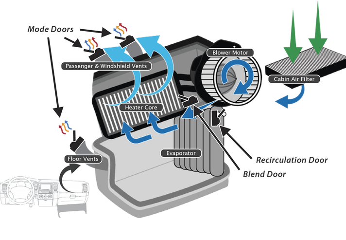
Similar to the design changes described in gpd Tech Tip #1, “Late Model Condensers”, late model A/C system evaporators have also been redesigned for improved efficiency. The evaporator is generally located in an HVAC unit behind the dashboard alongside the heater core, blower motor, and actuator doors. When the A/C system is on, low temperature refrigerant is cycled through the evaporator. The blower motor pushes air across evaporator, cooling the vehicle cabin.
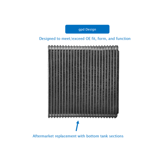
The evaporator style described in the following diagram is commonly referred to as a “twin pack” due to its dual chamber design. The “twin pack” evaporator design features 6 distinct sections separated by baffles. This creates a greater surface area for refrigerant to disperse across which greatly enhances heat exchange. Because refrigerant has to make several passes through each of these separated sections, the evaporator is able to maintain a constant temperature. |
|
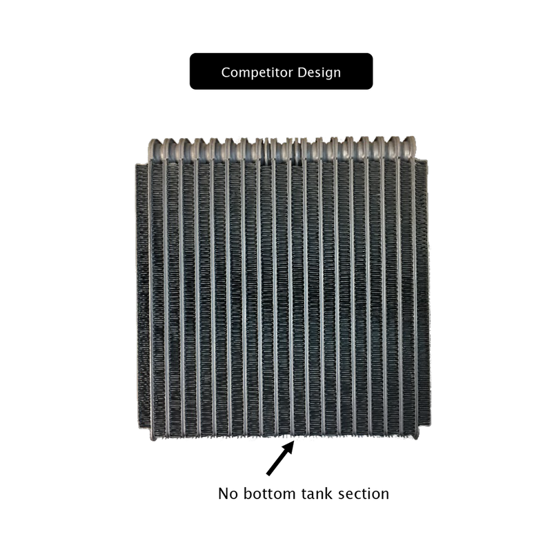
There are some cheaper products that are in the market that do not offer the same design or refrigerant flow. They may create a cooling issue, because the refrigerant will not have the same amount of surface area to generate heat exchange. They may also put the air conditioning system in to an overcharge situation, because modern systems take less refrigerant, so the smallest of overcharges has a large impact on the system.
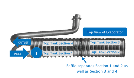
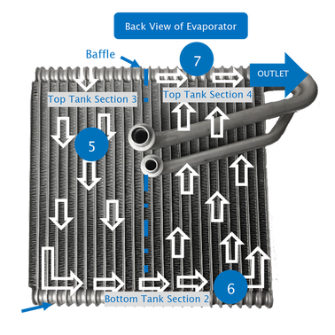
Refrigerant Flow in a Late Model “Twin Pack” Evaporator
|
1. Refrigerant enters evaporator through inlet, flowing into Top Tank Section 1.
|
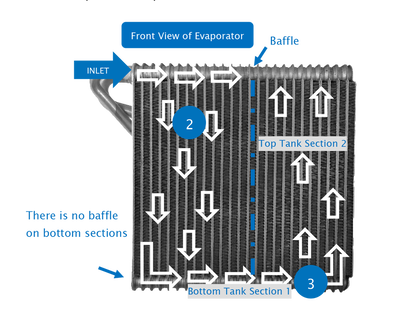
2. Refrigerant flows down the front side to Bottom Tank Section 1
3. Refrigerant flows across Bottom Tank Section 1, then travels upward to Top Tank Section 2 on the front side of the evaporator.
|
|
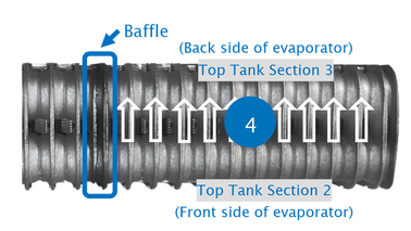
4. From Top Tank Section 2, refrigerant flows to Top Tank Section 3 on the back side of the evaporator.
5. Refrigerant flows down from Top Tank Section 3 to Bottom Tank Section 2 on the back side of the evaporator.
6. Refrigerant flows across Bottom Tank Section 2, then travels upward to Top Tank Section 4 on the backside of the evaporator. 7. Refrigerant exits the evaporator through the outlet attached to Top Tank Section 4. |
|
Please note: Some aftermarket options may not include the bottom tank sections. Cooling performance will be noticeably reduced without the bottom tank sections because the refrigerant will have a small surface area to disperse heat. If the system is sensitive to over/undercharge (requiring 4 oz. or less refrigerant charge), the absent bottom tank sections may cause the system to fail dure to overcharge.
|
|

|

|
| gpd_tech_tip_74-evaporator-late_model_design_with_baffles.pdf |